

Best Test Connector Types That Ensure Accurate Results
2026-11-16
Accurate results don’t start at the instrument—they start at the connection. A poorly chosen test connector can quietly introduce resistance shifts, thermal drift, and signal reflections that look like real data problems. Choosing the right type for the job is what separates measurements you can defend from ones you’ll have to repeat. At REUNION, we’ve seen how the right connector pairing keeps test setups stable from first contact to final readout. Below, we explore the connector types that genuinely protect accuracy—and why they deserve more attention than they usually get.
Shielded Connectors Stop Noise Before It Skews Readings
Electrical noise has a habit of finding the weakest link in a measurement chain. Shielded connectors are built to close that gap, using a continuous metallic enclosure that surrounds the contact points from cable to instrument. This barrier intercepts stray electromagnetic interference before it can superimpose itself on the signal, keeping tiny voltage or current fluctuations from masquerading as real data. Without that protection, readings can drift or jump in ways that look suspiciously like sensor behavior, leading to false alarms and wasted troubleshooting time.
The key is maintaining the shield’s integrity through the entire mating cycle. A properly designed shielded connector grounds the outer shell ahead of the signal pins during insertion, then keeps the connection tight under vibration or thermal cycling. Poorly fitted shields, by contrast, can act like antennas, picking up noise from nearby motors, relays, or switching power supplies and feeding it directly into the input stage. Technicians often notice the difference after swapping an unshielded connector for a shielded one: baseline noise drops, and faint signals that were previously buried in interference become readable.
Shielding is not a cure-all, but it removes one of the most common variables in precision measurement. It works best when the connector, cable braid, and instrument chassis all share a low-impedance path to ground, forming a complete Faraday cage around the signal path. In environments with high common-mode voltages or fast digital switching nearby, that continuity is what separates a stable reading from one that wanders whenever a nearby machine cycles on.
Coaxial Choices That Hold Signal Integrity Under Load
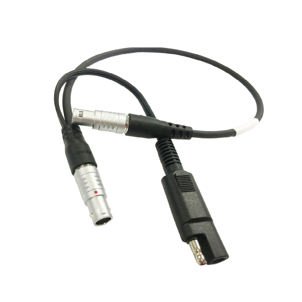
Under real mechanical load, coaxial assemblies flex, compress, and shift in ways that bench measurements rarely capture. The first place to look is the shield: a sparse braid that measures fine on a static network analyzer can open up under bending strain, letting external fields leak in and raising the noise floor. Solid outer conductors or high-coverage served shields with a bonded foil layer tend to hold their transfer impedance more consistently when a bundle is pulled tight or routed around a chassis corner.
Connector mating surfaces deserve equal attention, because load is rarely just axial. Vibration and thermal cycling create micro-motion at the interface, and small gaps quickly become reflection points. Choosing connectors with spring-loaded center contacts, consistent plating thickness, and enough outer-conductor engagement to resist rocking makes a measurable difference. The goal is not just a good initial VSWR but a contact system that stays quiet and stable after hundreds of thermal swings.
It also helps to test the cable exactly as it will be installed. Pull it around a mandrel, add a tie-wrap, warm it up, and then watch return loss under that condition. A coaxial choice that stays within its impedance window while loaded—rather than only on a straight, unstrained table—will prevent many intermittent faults that only appear after the system is buttoned up.
Spring-Loaded Probes for Repeatable Contact on Dense Boards
On tightly packed boards where test pads sit fractions of a millimeter apart, spring-loaded probes earn their place by turning fragile point contact into a repeatable mechanical routine. The internal spring absorbs overtravel and uneven board height, while the plunger keeps a steady wiping action across the pad. That small lateral scrub cuts through flux residue and oxide films, giving every cycle a clean electrical path instead of relying on luck or operator feel.
Getting consistent results at dense pitch is less about spring pressure alone and more about matching the probe tip to the pad geometry. Crown and spear tips work well on flat test points, but sharper styles can bite into solder or via edges when alignment drifts. Pairing shorter probe bodies with properly aligned guide plates reduces lateral deflection, and using dual-stage springs helps keep force stable across a full tray of boards rather than rising sharply with overtravel.
Material choices become critical once cycle counts climb. Beryllium copper plungers with hardened gold-over-nickel plating hold up far better than bare brass, especially in fixtures that see thousands of insertions a week. Regular cleaning of the probe tips and replacing worn springs before force curves flatten out keeps the contact resistance low and the measurement data trustworthy on high-density targets.
Banana Plugs Built for Low Resistance, Not Just Convenience
Most banana plugs stop at the idea of a quick push-in connection. This design starts at the conducting path itself. The body is machined from a single piece of high-purity copper alloy and then given a heavy gold plate, which keeps the signal from fighting a stack of dissimilar metals. The result is a plug that reads less like a convenience accessory and more like a short, clean extension of the cable.
The contact section uses an expanding center pin rather than a simple folded spring leaf. Once inserted, it exerts steady radial pressure against the jack wall, holding the mating surfaces tight through micro-vibration and repeated use. That pressure keeps the current flow spread across a broader contact area, so resistance does not creep upward after the first few connections.
In practice, that stability matters more than a snap-in feel. Low, repeatable resistance reduces the chance of muddy low end, smeared transients, or heat buildup at the connector when the system is driven hard. The plug remains easy to use, but the ease was not allowed to compromise what the electrical joint is actually doing.
PCB Test Points That Survive Probing Without Drift
A test point that shifts value after a few dozen cycles is worse than no test point at all. The usual failure is mechanical: the probe tip skates across the pad, shaves the surface finish, and gradually cuts into the copper. Once the plating is breached, oxidation raises contact resistance and measurements start wandering. To keep readings stable, the target has to be large enough for the probe to land cleanly and durable enough to take repeated strikes without wearing through. A flat, well-defined pad with a hard surface beats a tiny via or a random section of bare trace every time.
Surface finish does more work here than most designers expect. ENIG holds up reasonably well, but hard gold plating is the better choice when a board will be probed repeatedly on a production line or in field service. Avoid relying on bare copper or thin immersion tin; both tarnish quickly and turn a stable test point into a noise source. Pad dimensions matter just as much. A round or square pad in the 0.8 mm to 1.2 mm range gives the probe tip room to land without sliding off, and the solder mask opening should be slightly larger than the copper so the edges stay clean and fully exposed.
Mechanical anchoring is the part that gets overlooked. A test point dangling at the end of a long, narrow trace will flex under spring pressure, crack, or lift after enough cycles. Tie the pad to nearby copper with short, wide traces, and add teardrops where the trace meets the pad. If the board layout allows, place a few vias around the pad to lock it to the substrate and reduce deflection. Keeping test points away from flex zones and board edges also helps, because even a small amount of board bow can make the probe skate instead of compress.
Thermocouple Connectors That Keep Material Mismatch Out of the Reading
A thermocouple reading is only as trustworthy as the junction where two dissimilar metals meet. When a connector introduces a third material into that circuit, even a tiny difference in composition can generate its own micro-voltage and quietly distort the signal. This is why plugs and jacks built from the exact same alloys as the thermocouple wire itself are not just a convenience, they are a safeguard against invisible measurement drift.
In practice, a mismatched connector often shows up as a subtle offset that shifts with ambient temperature changes near the plug. One minute the readout looks stable, the next it drifts by a degree or two because the connector body warmed up or caught a draft. By using true thermocouple-grade pins, the cold junction compensation sees a cleaner path and the instrument stops fighting a phantom temperature source.
The real advantage comes during long logging runs or when panels are swapped frequently. A connector made from compensated alloys keeps every disconnect and reconnect from becoming a new source of error. Often the fix is as simple as matching the plug color code to the wire type and confirming the pins are stamped from the correct material, which saves hours of chasing readings that never quite settle.
FAQ
BNC connectors lock quickly and keep a constant impedance through the connection, which reduces signal reflection at lower frequencies. The bayonet coupling also prevents accidental pull-outs during bench testing, so readings stay stable without constant re-seating.
SMA connectors have a threaded interface that holds mating surfaces under consistent pressure, which matters when wavelengths get short. They also introduce less parasitic capacitance and inductance than many quick-connect types, helping preserve signal integrity above several gigahertz.
Kelvin clips are the better pick when you are measuring low resistance or high current paths. They separate the force and sense leads so the meter sees the device under test rather than the voltage dropped across the clip contact, avoiding inflated readings.
Plating changes contact resistance and long-term stability. Gold plating resists oxidation and keeps a low, stable contact resistance in low-voltage signals, while silver or nickel can handle higher mating cycles but may develop oxides that add tiny voltage offsets.
They can be, but only if the plugs and jacks are clean and tight. A worn banana jack adds a variable series resistance that becomes a problem with high-impedance or low-level signals, so for precision work it is often safer to use a shielded or guarded connection.
Shielding prevents outside electric fields from coupling into the measurement path. A well-grounded shell around the center conductor keeps interference from fluorescent lights, motors, or nearby digital lines out of the signal, which is especially important for low-level analog tests.
Pogo pins provide a spring-loaded contact that compensates for small board variations and repeated engagement. That means an automated fixture can make thousands of cycles without wearing down pads as fast, maintaining consistent contact force and reducing false failures.
Look for intermittent readings, rising contact resistance, visible wear or oxidation, and loose mating. In RF work, an increase in return loss or unexplained signal drop-outs often points to a connector that is worn or not fully seated.
Conclusion
Accurate measurements often fall apart at the connection, not inside the instrument. Shielded connectors are the first line of defense: they stop radiated noise from coupling into the signal path before it masquerades as real data. When the signal is high-frequency or must travel under load, coaxial choices matter just as much. A well-matched coax keeps impedance steady, so the waveform that arrives is still the one you intended to measure. On dense boards, spring-loaded probes earn their place by delivering repeatable contact without excessive pressure or skating across pads. That consistency reduces the tiny resistance shifts that can look like circuit drift.
Banana plugs, often treated as a convenience, are better understood as low-resistance links that keep the source and instrument at the same electrical potential. PCB test points need to survive repeated probing without moving or developing oxide layers that change contact resistance. A mechanically stable point with the right plating resists drift over dozens or hundreds of cycles. Thermocouple connectors add another layer: they use pins made from the same alloys as the thermocouple wire, so the connector itself does not introduce a parasitic junction that distorts the temperature reading. None of these pieces works in isolation. The most accurate setup treats the connector as part of the measurement circuit, not an afterthought, and selects each type for the specific electrical, mechanical, and thermal stress it will face.
Contact Us
Contact Person: Hayley Liang
Email: [email protected]
Tel/WhatsApp: +86 13480625451
Website: https://www.reunion-china.com/