

Custom Cleanroom Facility Design Essentials for Advanced Manufacturing
2026-08-15
Most cleanroom failures don’t start with a faulty fan filter unit—they start with a floor plan that ignores how operators actually move. In advanced manufacturing, custom cleanroom design has to align pressure differentials, material flow, and real-time monitoring from day one. At GENO Pharmatech, we approach every layout as an operational system, not just a controlled box. Here’s what to prioritize before you pour the slab or spec the first air handler.
Where Airflow Patterns Go Wrong in High-Precision Facilities
Airflow in high-precision facilities rarely fails because the design velocity is wrong on paper. It fails when a laminar flow field meets a rack of equipment that wasn’t in the original CFD model, or when a technician props open a pass-through door for a few minutes to move material. The resulting vortices pull particles from the floor or from operator gowning areas straight into the clean zone, even though the average air changes per hour still read within specification. Hot tools create thermal plumes that defeat downward displacement, and poorly placed return grilles then pull contaminated air sideways across the product.
Pressure cascades are another common failure point. A room that was balanced at commissioning can slip out of spec when filters load unevenly or when a neighboring lab changes its exhaust rate. The real problem is rarely the fan capacity; it’s the unsealed penetrations and worn door gaskets that turn a designed 15 Pascal differential into a flickering near-zero condition. Once that happens, air moves through the path of least resistance, which is often the service chase or the gap under a sliding door, not the intended supply-to-return path.
Monitoring systems can also mask these issues. A particle counter placed in the middle of the room will miss a dead zone behind a large instrument or a region where supply air short-circuits directly to a low wall return. Until someone runs a smoke study under realistic operating conditions, the facility can appear stable while product quality drifts. The fix usually isn’t more airflow; it’s moving returns, readjusting diffuser throw, or adding localized exhaust where heat and contamination actually originate.
Surface Finishes That Minimize Particle Release—Not Just Look Sterile
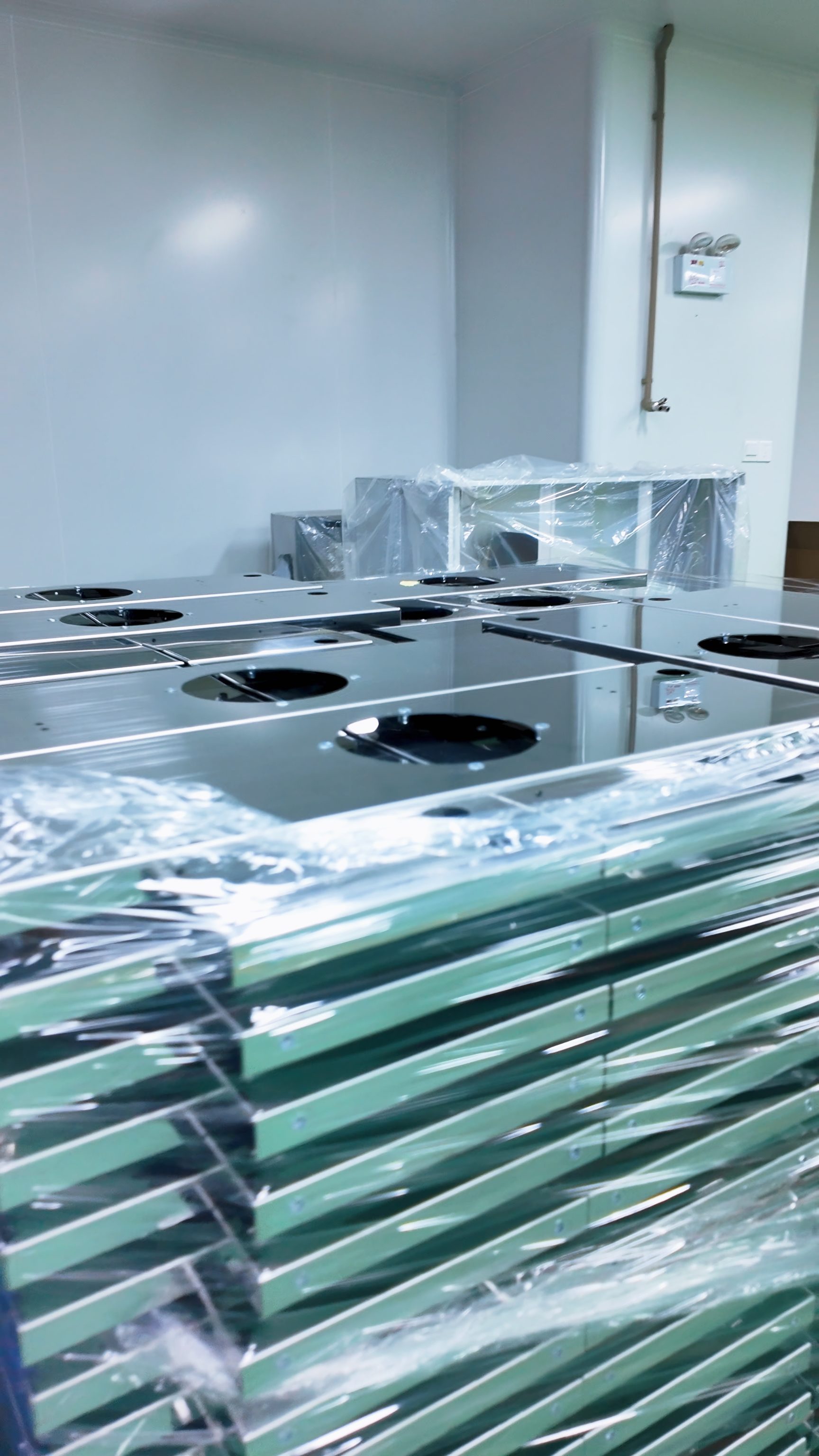
A surface can look immaculate under bright lights yet still shed enough microscopic debris to compromise a controlled environment. The real issue isn't visual cleanliness but how the material responds to repeated wiping, chemical exposure, and thermal cycling. Many finishes that appear smooth actually harbor micro-fractures where particles accumulate and later break loose, making a purely cosmetic assessment dangerously incomplete.
To genuinely cut down particle release, the focus shifts to finishes that resist degradation at the microscopic level. Electropolished stainless steel, for instance, removes surface irregularities and leaves a corrosion-resistant oxide layer that doesn't flake off under routine contact. Similarly, certain plasma-treated polymers develop a cross-linked surface that holds its integrity far better than painted or powder-coated alternatives, which often chip at edges and become hidden particle sources.
Validation matters more than appearance. Facilities that prioritize low particle shedding typically run periodic surface particle counts and roughness measurements instead of relying on a simple visual sign-off. They also test finishes after hundreds of wipe-down cycles, since a material that starts out clean can degrade into a particle emitter once its protective top layer begins to wear. This kind of ongoing verification separates surfaces that merely look sterile from those that actually help keep a space clean.
Pressure Cascade Strategies for Multi-Room Manufacturing Suites
Pressure cascades in multi-room manufacturing suites are less about hitting a single setpoint and more about shaping how air moves when doors open, filters load, or exhaust systems drift. A well-designed cascade uses the offset between supply and return/exhaust air to push flow from higher-grade zones toward lower-grade ancillaries, so any airborne particle or vapor has a predictable path away from critical operations.
Achieving this across several interconnected rooms usually requires a mix of hard physical elements and responsive controls. Supply air for the cleanest suites is intentionally over-delivered relative to exhaust, while surrounding buffer rooms run closer to neutral or slightly negative. Differential pressure sensors modulate VAV dampers on individual branches, and airlocks or material pass-throughs act as pressure breakers. Design targets commonly range from 10 to 15 Pa between adjacent classifications, but the exact values depend on door size, traffic frequency, and whether the suite handles hazardous compounds that demand containment.
The real test of a cascade strategy is how it behaves during routine movement and maintenance, not steady state. Opening an interlocked gowning room door can momentarily collapse a differential and even reverse flow if the control loop is too slow. To avoid that, many facilities implement zoned cascades where the innermost aseptic core sits at the highest pressure, with step-downs through buffer zones to unclassified corridors. Regular smoke studies and pressure decay testing help verify that the intended airflow direction holds under door cycling and filter loading conditions, since static gauge readings alone can miss transient reversals.
Why Modular Walls Outperform Fixed Construction in Fast-Paced Plants
In a production environment where line layouts shift with every new product cycle, tearing down drywall or block construction simply isn't an option. Modular walls are engineered for reconfiguration—panels unbolt and relocate within hours, not weeks. That agility means a packaging area can become a cleanroom enclosure by the next shift without dust, debris, or structural compromise. It's not just about speed; it's about keeping the plant running while the space evolves around the work.
Fixed construction also locks you into sunk costs. Once that concrete wall goes up, any future change requires demolition, permits, and downtime that eats into throughput. Modular systems sidestep this entirely: they arrive pre-finished, install with basic tools, and can be depreciated as equipment rather than real estate. For plant managers balancing capex with the constant pressure to adapt, that financial and operational flexibility is the difference between keeping pace and falling behind.
Vibration Isolation Techniques for Sensitive Tooling and Metrology
Understanding the vibration spectrum of the floor is usually the first step in selecting isolation for precision equipment. In semiconductor lithography or ultra-precision diamond turning, even nanometer-scale displacements can scrap a part or distort a measurement. Passive isolators—air springs, wire rope, elastomer pads—excel at attenuating higher frequency chatter from pumps and HVAC systems, but they often struggle below a few hertz. That low-frequency sway, common in multi-story buildings, demands active feedback systems that sense motion and counter it with force actuators. The real decision hinges on damping and settling time, not just static stiffness, because a poorly damped isolator can ring for seconds after a load change, corrupting the very measurement it was meant to protect.
A more reliable approach often combines structural decoupling with empirical floor characterization. Instead of placing a coordinate measuring machine directly on the slab, many facilities pour a dedicated inertia block or use tuned mass dampers to push the system's natural frequency away from the ambient excitation. Before committing to a commercial isolator, accelerometers are placed at the planned mounting points to record the actual vibration signature. That data determines whether a laminar-flow air isolator will suffice or whether a piezoelectric active stage is necessary to handle coherent low-frequency peaks. Skipping this step is risky: an isolator whose resonance happens to align with the floor's dominant mode will amplify, not reduce, the disturbance.
Active isolation has matured considerably, with modern systems using geophone or force feedback to cancel disturbances down to roughly 0.5 Hz. These platforms employ voice-coil actuators and real-time digital controllers, but integrating them into a metrology frame introduces subtle problems. Actuator heat can create thermal drift that mimics low-frequency vibration, and stiff cables can short-circuit the isolation by transmitting vibration directly. In practice, the best results come from a rigid, well-damped mechanical path combined with an active loop that only corrects what the passive elements cannot handle—leaving the system stable, quiet, and predictable over long measurement cycles.
Cutting Energy Use Without Opening the Door to Contamination
Many facilities that handle sensitive processes—whether pharmaceutical production, food packaging, or hospital isolation rooms—have long assumed that more airflow equals better protection. This mindset leads to oversized fans running at full speed around the clock, even when the actual contamination risk is low. A better starting point is to map real occupancy and activity patterns. For example, a cleanroom used for batch production might sit idle for hours each day, yet its air handling system continues to supply the same volume of filtered air as during active work. By tying ventilation rates to actual need, you can cut fan energy dramatically without compromising cleanliness, provided that room pressure differentials and particle counts are continuously verified.
Variable frequency drives (VFDs) on supply and exhaust fans are often the fastest win. Instead of running motors at a constant 60 Hz, a VFD can ramp down airflow during low-load periods while keeping the room at the required positive or negative pressure. The key is to install reliable particle counters and pressure sensors that feed data back to the building automation system. If particle counts stay below threshold and pressure remains stable, the system holds the lower speed. If any parameter drifts, the fans automatically ramp back up. This closed-loop approach removes the guesswork and prevents the classic failure mode where a well-intentioned energy-saving measure quietly opens a path for contamination.
Another overlooked strategy is improving the sealing and layout of the space itself. Leaky door gaskets, poorly fitted ceiling panels, and unsealed penetrations force HVAC systems to work harder to maintain pressure and cleanliness. Tightening these paths allows you to reduce total airflow without losing containment. Additionally, consider heat or energy recovery from exhaust air—but only with systems designed to prevent any cross-contamination, such as run-around coils or segregated plate exchangers. Even small adjustments, like scheduling night setbacks that keep pressure differentials intact but lower air changes, can deliver measurable savings. The goal is not to weaken protection, but to stop paying for air movement that provides no real safety benefit.
FAQ
Advanced manufacturing often involves unusual tool sizes, vibration-sensitive processes, hazardous chemistry, or extreme cleanliness levels. A standard modular room can't always accommodate a 12-foot-tall deposition tool or isolate a wet bench from a photolithography bay. Custom design lets you shape airflow around the actual equipment layout, place exhaust and gas lines where they won't create dead zones, and match the floor loading to heavy process tools. It's less about choosing a cleanroom package and more about engineering the room as part of the production line.
It starts with the process map. If the line includes solvent handling or powder dispensing, you may need directional air and local capture more than raw air changes. For ISO 5 zones under laminar flow, you typically plan 300 to 600 fpm uniform velocity, but adjacent ISO 7 areas can run far fewer air changes if the contamination sources are confined. The trick is to model the contaminant release points and set return air locations there, rather than blanketing the whole floor with high ACH. Fan filter coverage, ceiling height, and tool exhaust all shift that number, so a fixed air changes per hour rule usually misses.
Walls and ceilings should be non-shedding and chemical-resistant, but not every room needs an expensive FRP or stainless finish. For most advanced manufacturing, an aluminized or PVC-coated panel with sealed joints works, provided it can handle the wipe-down chemicals. Flooring needs to withstand rolling loads and occasional acid spills; epoxy or urethane systems with coved edges reduce particle traps. Ceiling tiles must be non-friable and gasketed if you run a pressurized plenum. Avoid anything with exposed wood, unsealed concrete, or standard drywall in a process area.
Run process piping and electrical conduit in a service chase above or beside the cleanroom, never surface-mounted unless it's quick-connect process gas lines. Penetrations should use sealed escutcheons, and any duct that passes through the shell needs a low-outgassing sealant. For gases and water, use orbital-welded stainless or high-purity polymer lines, with drops entering through a utility panel rather than breaching the clean wall at random points. The key is to keep the clean side as smooth as possible and put all maintenance access on the dirty side.
Plan the shell and air handling for the worst-case cleanliness class you might need in five years. Leave spare capacity in the make-up air unit and electrical panels. Design the ceiling grid so fan filter units can be added or moved without reframing. Keep the floor layout modular, using removable partitions rather than structural walls for zones that are likely to change. You don't need to build empty bays, but you should avoid locking process-specific chases into the slab if there's any chance of a tool layout shift.
In a custom room, the air patterns and pressure cascades are tailored to specific tools, so small changes can have big effects. A door left open, a clogged prefilter, or a tool exhaust going down can reverse the pressure differential between a wet process and a dry litho bay. Real-time particle counters and pressure monitors catch drift before it becomes yield loss. You want the monitoring points placed at the actual risk locations, such as return air near a furnace or an autoclave, not just on a wall by the door. Data logging also helps when an audit asks why a lot was released weeks after a pressure alarm.
One is over-specifying cleanliness in the whole room when only one tool station requires ISO 4. Another is forgetting maintenance clearances; a cleanroom that can't slide a pump out for service will end up being shut down for repairs that could have happened from the chase. Poor vibration isolation for lithography or metrology tools is also common, because the slab might be adequate for particle control but not for 1,000-pound moving stages. Finally, skipping a proper pressurization cascade can let humid or particle-laden air from a cleaning area flow into a sensitive zone.
Conclusion
In advanced manufacturing cleanrooms, certification alone rarely predicts performance—most failures trace back to airflow patterns that look correct on paper but create dead zones in practice. Equipment loading, tool exhaust, and even walk paths can disrupt unidirectional flow, letting particles hover near critical surfaces instead of being swept away. Pair this with poorly staged pressure cascades, and contamination migrates from less clean zones into core process areas through door swings or cable penetrations. The fix demands room-by-room differential monitoring, interlocked pass-throughs, and supply air balanced so the cleanest suite always pushes outward. Surface choices matter just as much: electropolished stainless, seamless epoxy, and polyurethane finishes with coved corners reduce particle shedding and tolerate aggressive wipe-downs without micro-cracking. A wall that merely looks sterile but traps particles in seams or outgasses under UV exposure will eventually compromise the product, so finish selection must be driven by cleanability data rather than appearance.
Modular wall systems have become the default for plants that expect process changes every few years. Unlike fixed drywall or epoxy-coated block, demountable panels with integrated utility chases allow tool moves and room reclassification in days instead of months, and they avoid demolition dust that can shut down adjacent production. Vibration control is equally non-negotiable where electron microscopes, aligners, or interferometers sit near HVAC equipment or foot traffic. Passive air isolators handle high-frequency disturbances, but low-frequency building sway often requires active cancellation or isolated slabs with tuned mass damping. As for energy, the old habit of cranking air changes to "be safe" wastes power and actually increases particle shedding from fan belts and duct erosion. Modern designs use variable-speed fan filter units, low-pressure-drop HEPA/ULPA media, and demand-based airflow reset during idle shifts—while holding pressure cascades and recovery rates tight enough that saving energy never becomes an excuse for letting the cleanroom breathe backward. Sensor placement at return-air paths and critical zones validates that reduced airflow still meets particle counts under dynamic conditions.
Contact Us
Contact Person: Amy Yang
Email: [email protected]
Tel/WhatsApp: 008619330882686
Website: https://www.genopharmatech.com/