

Lightning Strike Current Sensor Manufacturer Essentials for Reliable Monitoring
2026-08-23
Lightning doesn’t wait for weak links to fail—it finds them. If reliable monitoring is your responsibility, the current sensor isn’t just another component; it’s the first line of defense against data loss when a strike hits. But not all sensors are built to survive that split second. Choosing a manufacturer who understands the brutal physics of lightning—like Xiasen—can mean the difference between a clean data stream and a blind spot in the storm. Here’s what to look for before the next bolt.
What Separates a Reliable Lightning Strike Current Sensor from the Rest
Lightning current is not a tame signal. A strike can rise from zero to tens of kiloamperes in microseconds, carrying significant energy across a frequency spectrum that extends well into the megahertz range. A reliable sensor must track that abrupt leading edge without saturating, clipping, or adding ringing of its own. Off-the-shelf current transformers with modest bandwidth and ferrite cores often fall short here, either because the core enters saturation and smears the waveform, or because parasitic capacitance limits the high-frequency response. The sensors that hold up are usually built around air-core or low-permeability designs with a genuinely wide bandwidth, paired with analogue front-ends able to handle large di/dt values without running out of headroom.
The environment around a lightning strike is hostile in ways that laboratory tests rarely capture. A direct or nearby strike creates an intense electromagnetic pulse that can induce currents in cables, connectors, and even the sensor housing itself. A dependable sensor therefore needs more than good specifications on paper; it needs shielding, careful grounding, and signal routing that rejects common-mode interference. Differential measurement paths, galvanic isolation, and fibre-optic links to the data acquisition system help keep the wanted signal intact while the rest of the installation is being hammered by induced transients. Mechanical construction matters too. Outdoor-rated enclosures, sealed connectors, and UV-stable materials prevent slow moisture ingress or corrosion from degrading performance over years of exposure.
Long-term trust comes from evidence, not marketing. A sensor that reads correctly on a bench with a low-energy impulse generator may behave differently when exposed to repeated full-scale strikes, thermal cycling, and salt spray. Reliable devices are validated against traceable impulse current standards, often with multiple shots at increasing amplitude, and they demonstrate tight consistency from shot to shot. After installation, the best systems include built-in health checks, such as injection of a known calibration signal or continuous monitoring of offset and gain drift. This makes it possible to know, before storm season arrives, whether the sensor is still telling the truth rather than simply assuming it is because the last maintenance visit found no visible damage.
Why Enclosure Design Determines Sensor Survival in the Field
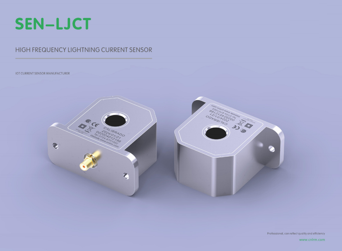
A sensor's electronics can be flawless on the bench and still fail within weeks outdoors if the enclosure does not account for thermal cycling. Polycarbonate housings expand and contract at a different rate than the metal inserts and O-rings they mate with, opening microscopic gaps that pull in moisture during night-time cooling. Once condensation reaches the circuit board, corrosion and parasitic leakage begin long before any visible water intrusion is noticed.
The same logic applies to chemical exposure. A sealed aluminum housing may survive a salt spray test but degrade rapidly around a fertilizer storage area, where ammonia vapor attacks the anodized layer and causes pitting at the threads. Designers who rely only on an IP rating without checking material compatibility often learn this after a batch of sensors returns from the field with brittle cable glands and fogged lenses.
Mechanical protection matters just as much as environmental sealing. In agricultural or heavy equipment settings, enclosures get hit by stones, tools, and vibration. A thin-walled plastic shell may keep water out on day one, but a hairline crack from impact becomes an open door for humidity. Field survival depends on selecting a housing that absorbs or deflects that abuse while still allowing the sensor to be serviced without breaking the seal.
Surge Testing Beyond Standard Waveforms for Real-World Confidence
Standard surge testing typically relies on the 1.2/50 microsecond open-circuit voltage and 8/20 microsecond short-circuit current combination wave. But real transients on power lines are rarely this tidy. Motor starts, indirect lightning effects, and capacitor bank switching generate far more complex events, including oscillations, repetitive pulses, and varying source impedance. Relying on a single standard waveform can let a product pass in the lab yet fail in the field.
Going beyond standard waveforms means testing at different phase angles, applying multiple pulse sequences, and mixing in waveforms like the 0.5 microsecond / 100 kHz ring wave. Injecting surges at both the peak and zero crossing of the AC mains mimics the worst-case conditions that real equipment encounters. Real-world confidence comes from covering these abnormal scenarios, ensuring protection devices can clamp and absorb energy even when the transient is far from textbook.
Some engineering teams now use programmable surge generators capable of synthesizing arbitrary waveforms or replaying transients captured in the field. This shifts testing from a simple compliance check to genuine design verification, uncovering weak points that standard tests miss, such as PCB trace inductance or component aging. Ultimately, investment in non-standard surge testing translates directly into lower field failure rates and longer product life.
The Hidden Impact of Material Fatigue on Long-Term Accuracy
Most discussions around precision instruments focus on calibration schedules, environmental controls, or operator technique. Rarely does the conversation drift toward the silent, gradual degradation of the materials themselves. Yet every load cycle, thermal shift, and microscopic vibration leaves a fingerprint on the crystalline structure of metals and polymers. Over months and years, these fingerprints accumulate into measurable dimensional drift—not from any single dramatic event, but from the relentless repetition of ordinary use.
Consider a high-end CNC spindle or a laboratory balance. The alloy components may look identical to the day they were installed, but internal stress redistribution quietly alters their elastic response. A spring that once returned to within 0.002 mm of its original position might now settle 0.005 mm off, even under identical force. That tiny shift propagates through the measurement chain, eroding confidence in results that users still assume are rock-solid. The insidious part is that no error message appears; the instrument simply becomes less trustworthy over time.
Engineers often treat material fatigue as a failure-mode issue—something to prevent catastrophic cracks or fractures. But long before visible damage occurs, fatigue manifests as subtle changes in stiffness, damping, and hysteresis. These changes directly affect repeatability and long-term accuracy. The fix isn't necessarily exotic alloys or frequent recalibration alone; it's acknowledging that material behavior is a living variable, not a fixed constant, and designing maintenance protocols that monitor drift rather than assuming stability.
Calibration Drift and How to Keep Readings Trustworthy Over Time
Calibration drift sneaks up on you. It is not a dramatic failure but a slow, quiet shift in sensor response that gradually pulls readings away from the true value. Temperature swings, humidity changes, mechanical vibration, or simply the aging of electronic components can all nudge an instrument out of alignment. The first sign is often subtle: a value that looks plausible but is slightly off, a measurement that no longer matches a known reference. If left unchecked, the error compounds, and decisions based on those numbers start to lose their footing.
The practical defense is a regular verification routine against trusted standards, not just a yearly calibration sticker. Keep a log of drift trends for each critical sensor—many small deviations over weeks tell you more than a single out-of-tolerance flag. Use check standards or reference materials that bracket the range you actually measure, and run them at intervals short enough to catch drift before it matters. In field settings, consider environmental compensation: if temperature is the main culprit, monitor it alongside the sensor and apply a correction only when the drift pattern is well understood.
Trust in readings is built on small, consistent habits. Document every adjustment, no matter how minor, and include the conditions at the time. When a sensor drifts repeatedly in the same direction, investigate the root cause instead of just tweaking the output—perhaps the mounting has loosened or the electronics are nearing end of life. Teach operators to recognize a suspicious reading as a prompt for verification, not a reason to panic. Over time, this approach turns drift from an invisible threat into a manageable, predictable variable.
Field Integration Mistakes That Undermine Monitoring Accuracy
A frequent slip happens when field units and coordinate references get swapped during integration. A pressure transmitter may report in kilopascals while the monitoring dashboard expects pounds per square inch, and since neither side flags the mismatch, every threshold alert becomes meaningless. Similarly, timestamp handling often assumes both field logger and central server share the same clock; a few minutes of drift can push peak load readings into the wrong reporting interval.
Another recurring failure is treating device status codes as optional metadata. Many integration pipelines drop the quality flag from a Modbus register or ignore a sensor's 'maintenance needed' bit, then feed raw values straight into analytics. A flow meter that has been offline for two hours can show up as zero flow rather than a gap, dragging down daily averages and masking a real pump failure until someone checks the raw log.
Latency and sampling mismatches also quietly sabotage accuracy. Field devices often batch data and send it in bursts over unreliable networks, so joining readings by nearest timestamp can pair a temperature value from ten minutes ago with a current pressure spike. Without explicit interpolation rules or buffer windows, the merged dataset looks complete but actually hides systematic errors that grow with the number of integrated points.
FAQ
A dependable manufacturer pairs deep materials engineering with field-proven testing. They openly share failure thresholds, offer custom shielding options, and design sensors that stay linear even after repeated high-energy surges, rather than just quoting specs from a datasheet.
Material selection dictates how the sensor handles thermal stress and electromagnetic interference. For instance, using high-permeability nanocrystalline cores with epoxy-free winding reduces partial discharge and drift, keeping measurements trustworthy through storm seasons and temperature swings.
Calibration must reflect real fault conditions, not just lab sine waves. A forward-thinking manufacturer verifies response against 8/20 µs and 10/350 µs waveforms, then documents how the sensor behaves near saturation, so you know the exact range where readings stay credible.
Lead routing and grounding continuity are the usual culprits. If the signal cable runs parallel to down conductors or the shield is grounded at both ends creating a loop, induced noise can swamp the true current reading. Manufacturers who provide layout-specific guidance and isolation kits prevent these silent failures.
Ask for raw oscillographs from their impulse generator, not just pass/fail certificates. A credible manufacturer will show you the actual captured waveform against the reference shunt, including any overshoot or tail deviation, and explain the test setup's earthing arrangement in plain language.
Response time determines whether the sensor catches the steep front of the strike or smears it. A sensor that is too slow underreports peak current and misrepresents the energy let-through, which can lead to false confidence in downstream protection coordination. Look for sub-microsecond rise time under actual load impedance.
Condensation cycling and solar-induced temperature swings degrade potting compounds and connector seals faster than most expect. A thoughtful manufacturer designs for dew point excursions and UV exposure, using vented housings or humidity-hardened electronics so that morning fog does not become a data integrity problem.
While IEC 62305 and IEC 62561 give a baseline, forward-leaning manufacturers also align with utility-specific guidelines like IEEE C62.45 for surge testing. The key is that they use standards as a floor, not a ceiling, and can explain deviations that improve performance in your particular grounding environment.
Conclusion
Lightning strike current sensors that hold up in the field are rarely defined by headline specifications alone. The difference often comes down to how well the manufacturer addresses the mechanical and environmental reality of the installation. Enclosure design, for instance, plays an outsized role: a housing that survives repeated thermal cycling, salt spray, and UV exposure without cracking or losing its ingress protection will protect the internal electronics far better than any conformal coating applied as an afterthought. Beyond that, surge testing must move beyond the standard 10/350 µs and 8/20 µs waveforms. Real lightning events are messy, often involving multiple return strokes, continuing currents, and superimposed oscillations. Sending a sensor through a single clean pulse gives a false sense of confidence. The most reliable devices are validated against a mix of fast fronts, long tails, and repeated transient bursts that mirror what a tower or substation actually sees.
Material fatigue and calibration drift are quieter failure modes. Repeated vibration from wind or nearby machinery, combined with daily temperature swings, can create micro-cracks in solder joints or shunt elements, gradually shifting the sensor's response. Without periodic verification, that drift goes unnoticed until a strike reading no longer matches the known current from a reference measurement. Field integration mistakes compound the problem: a poorly bonded ground, a cable routed parallel to power lines, or an incorrectly positioned current transformer can introduce enough common-mode noise to swamp the true signal. Manufacturers who supply clear, field-ready mounting kits, shielded cabling, and on-site calibration checkpoints give monitoring crews a fighting chance. Ultimately, reliable lightning monitoring is less about a single robust component and more about how the sensor, its enclosure, and its installation work together over years of neglect and extreme weather.
Contact Us
Contact Person: Liu Mengyang
Email: [email protected]
Tel/WhatsApp: 8618727589233
Website: https://www.cnlrm.com/en/