

OEM CNC Milling Machine Solutions for High Precision Custom Manufacturing
2026-10-02
Precision in custom manufacturing isn’t a feature you can bolt on after the fact—it’s engineered into every axis, spindle, and cutting path from the start. That principle drives WINNRUI CNC to design OEM milling machine solutions around the unforgiving demands of high-precision work, not generic machine specs. Whether you’re machining complex geometries or chasing micron-level tolerances, the right solution changes more than your scrap rate; it changes what your shop can confidently quote. Here’s what that looks like in practice.
Micron-Level Milling That Doesn't Fade After First Article
Most shops can hit a number on the first article. The harder part is hitting that same number on the five hundredth part, after the spindle has warmed up, the tool has worn a few microns, and the morning shift has given way to the night crew. That’s where our process is different: we don’t treat the first article as the finish line, but as the first data point in a running stability check.
The machines are mapped for thermal growth across a full production day, and the probing cycles feed actual part geometry back into the offset tables before drift can accumulate. Tool wear is tracked against cutting time rather than part count, and the fixturing is designed so clamping force doesn’t quietly distort thin walls or small features. When the environment shifts, the compensation shifts with it.
The result is a micron-level milling process that holds from the first article to the last part in the lot. You don’t get a beautiful CMM report on piece number one and a slow decline after that. You get repeatable geometry, run after run, without babysitting the machine or waiting for a quality alert to tell you something slipped.
Workholding Engineered Around Your Part's Most Fragile Feature
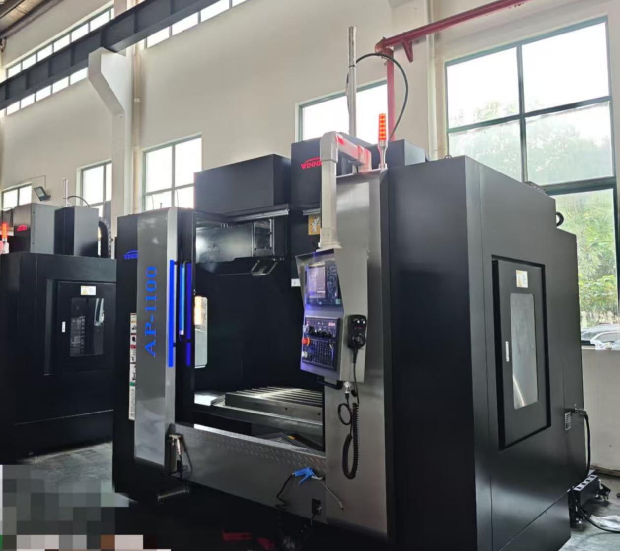
Every machinist has faced that moment when a delicate wall, a thin web, or a sharp internal corner threatens to crumple under clamping pressure. Standard vises and generic fixtures ignore those vulnerabilities, forcing you to compensate with light cuts, extra supports, or simply crossing your fingers. The real solution starts before you ever touch the spindle: designing the workholding around the geometry that's most likely to fail.
Instead of treating the part as a solid block that needs to be squeezed into submission, think of the fixture as a tailored cradle. The clamping forces get relocated away from fragile regions, often reversed or redirected into areas where the raw stock has extra material or where compression actually improves rigidity. For a thin-walled housing, that might mean holding from an internal boss with expanding mandrels rather than crushing the outer skin. For a bracket with a tiny, load-bearing tab, a custom nest supports that tab while the main clamp engages a thick, sacrificial pad left on the opposite side.
This approach doesn't just prevent cracked parts; it unlocks faster feeds and deeper cuts because the workpiece no longer buzzes or deflects where it matters. It also shortens setup time—no more shimming, re-tightening, or babysitting the first article. When the fixture respects the part's weakest link, you stop fighting the material and start machining with confidence.
Five-Axis Toolpaths That Cut Setups, Not Corners
Switching from three-axis to five-axis machining isn't just about adding two rotary axes. It changes how you think about holding a part. With three-axis work, a complex bracket might need four or five separate setups—each one introducing a fresh chance for misalignment. You clamp, indicate, cut, unclamp, flip, and repeat. Every re-fixture stacks tolerance on top of tolerance, and the witness marks where passes meet tell the story. Five-axis toolpaths let the cutter reach around corners and undercuts in a single clamping. That means fewer setup sheets, less downtime spent sweeping chips off fixture plates, and a part that comes off the machine closer to final form.
But trimming setups doesn't give you permission to blunt the toolpath in tight corners. The real craft lies in keeping the cutter engaged cleanly where walls converge or a fillet blends into a pocket floor. A lazy five-axis program will tilt the tool just enough to avoid a collision, then leave a scalloped mess or gouge the adjacent surface. Good toolpaths adjust the lead and tilt angles continuously, holding a steady chip load while the tool shank stays clear of the workpiece and clamps. That's the difference between cutting setups and cutting corners—you remove the extra handling without sacrificing the crisp geometry that made you choose five-axis in the first place.
Machining Exotic Alloys Without Burning Through Inserts
Shops often treat exotic alloys like Inconel or titanium as if they were just stubborn stainless steel. The result is predictable: inserts scorch at the cutting edge, chipping away before a single part is finished. But burning through inserts isn't a material problem—it's a process problem. Exotic alloys work-harden almost instantly, generate vicious heat at the shear zone, and punish any hesitation with built-up edge. The fix starts with ditching generic speeds and feeds. Drop surface footage lower than you think reasonable, keep the tool engaged, and use a sharper edge prep with a positive rake. You're not trying to force the metal off; you're guiding it off in thin, hot ribbons that carry the heat away with the chip instead of dumping it into the insert.
Coolant strategy matters more than most machinists admit. Flooding the cut with standard emulsion can cause thermal shock, cracking carbide as it cycles between hot and cold. High-pressure through-tool coolant aimed directly at the chip contact zone works better, but if that's not available, switch to a rich oil-based mist or cut dry with an air blast. The goal is consistent temperature at the cutting edge, not maximum cooling. For many shops, a switch to ceramic or CBN inserts at higher speeds actually reduces burning because the heat softens the workpiece just enough to shear cleanly. It sounds counterintuitive, but burning through inserts usually comes from moving too slow and letting heat soak into the tool instead of pushing it into the chip.
Toolpath decisions are the hidden knife in your budget. Conventional milling rubs the first part of every cut, work-hardening the surface before the tooth bites. Climb milling and trochoidal paths keep the cutter engaged at a consistent chip thickness, preventing the micro impacts that fracture edges. Same with turning: use a lead angle that thins the chip and spreads load along the edge rather than concentrating it at the nose radius. And don't overlook insert grade. A tough, uncoated carbide with a fine grain often outlasts a hard coated grade in nickel alloys because the coating flakes under heat cycling and drags chunks of substrate with it. If your insert wear photos look like crescent moons or notches at the depth-of-cut line, you're not machining the alloy—you're fighting it. Step back, drop the speed, tighten the engagement, and let the chip do the heavy lifting.
In-Process Inspection Feeding Live Offsets Back to the Spindle
Modern machining centers increasingly rely on direct feedback loops between measurement and motion control. During a cutting cycle, touch probes or laser scanners mounted near the work zone capture dimensional data on the fly. These readings are compared against the nominal geometry in real time, and any detected deviation is converted into a small positional correction. The corrected value is pushed directly to the spindle's control unit, which shifts the toolpath slightly for the next pass. This closed-loop approach eliminates the need to stop the machine for manual inspection, saving minutes on every part while maintaining tight tolerances.
The trick lies in how quickly the offsets are applied. Rather than waiting for a complete part to be probed after machining, the system samples critical features while chips are still flying. The spindle, acting as both cutting and sensing platform, receives offset updates through the CNC's high-speed internal bus. A drill that wanders a few microns due to tool wear gets pulled back on target within the same sequence. Over a batch of hundreds of parts, this continuous correction keeps the process centered, preventing drift that would otherwise show up only in a final inspection report.
Operators often notice that the process becomes quieter and more predictable. Instead of a series of scrapped parts revealing a worn insert, the spindle compensates gradually, and tool life data accumulates from the offset trend itself. For tight bores or mating surfaces, this in-process feedback can hold size to within a few microns without any human intervention. The end result is a machine that effectively tunes itself, using the spindle as both the source of error and the point of correction.
OEM Cells That Scale From Prototype to Full Production
Moving from a hand-built prototype to a continuous production line often exposes weaknesses that lab tests never reveal. Our OEM cells are designed around a fixed set of electrode dimensions, coating thicknesses, and winding tensions, so the same process window used for single-piece trials can be applied directly to high-speed equipment. No re-optimization of slurry viscosity or drying profiles is needed when you increase throughput from ten cells a day to ten cells a minute.
Consistency across large batches is where most cell suppliers stumble. We embed a traceable QR code on every can and link it to inline measurements from electrolyte filling, formation cycling, and final impedance checks. Closed-loop feedback adjusts welding pulse energy or electrolyte volume without human intervention, keeping capacity spread below ±1.5% even after 100,000 units. This approach eliminates the common practice of sorting and grading cells after production, which slows down delivery and inflates cost.
Scaling also depends on supplier-side readiness. We work directly with separator and electrolyte partners to qualify low-viscosity formulations compatible with 80-meter-per-minute coating lines, and we replaced manual tab welding with laser-positioned automation. As a result, a customer can move from a 200-cell pilot order to a 50,000-cell annual contract without changing the cell model or repeating safety certifications. The only variable that changes is the number of modules assembled, while the per-cell performance stays identical.
FAQ
Tight tolerances of ±0.005 mm are possible depending on geometry and material. We verify every batch with CMM inspection and share full dimensional reports so you can see exactly how each feature came out.
Yes, the same programming and fixturing approach is used from first article through repeat orders. That means a prototype that passes your review can move into production without changing toolpaths or setup logic.
Aluminum alloys, stainless steel, titanium, brass, and engineering plastics like PEEK and Delrin are all in regular use. We match cutting tools, coolant, and speeds to the specific material to keep surface finish and edge quality consistent.
In-process probing checks critical dimensions at set intervals, and tool wear is monitored automatically. Any drift triggers a tool change or offset adjustment before parts fall out of spec, so the first part and the last part stay within the same tolerance band.
Yes. Our engineers review your CAD model for thin walls, deep pockets, sharp internal corners, and hard-to-reach features. We suggest practical changes that lower cost or improve machinability without altering the function of the part.
We work with medical device makers, aerospace suppliers, robotics companies, and semiconductor equipment builders. Each field has different documentation and traceability needs, so we adapt the quality package accordingly.
All files are stored in access-controlled systems, and NDAs are standard before any technical discussion. Physical parts are handled only by cleared staff, and we can segregate your project on dedicated machines if required.
We focus on long-term manufacturing partnerships rather than one-off jobs. That shows up in process documentation, repeatable fixturing, raw material traceability, and a clear escalation path if a tolerance or finish issue ever appears.
Conclusion
Precision CNC milling for OEM work usually falls apart after the first article—thermal drift, fixture shift, tool wear all stack up quietly. We addressed that by building a process where micron-level tolerances hold across a full production run, not just on the validation part. The workholding is designed backwards from your part's most fragile feature: thin walls, tiny bosses, deep pockets get supported exactly where they need it, so clamping forces don't distort the geometry you spent weeks designing. Five-axis toolpaths then remove the need for multiple setups that invite stack-up error. By tilting the tool instead of repositioning the part, we cut the number of fixturing cycles and keep every feature referenced to the same datum. That combination of stable fixturing and single-setup machining is what makes consistent high-precision output possible on parts that would otherwise require constant babysitting.
Exotic alloys like Inconel, titanium, and hardened stainless punish generic cutting strategies with rapid insert wear and unpredictable surface finish. Here the approach centers on tuned speeds, controlled engagement, and coolant delivery that keeps heat out of the cut zone, so insert life goes from minutes to hours without sacrificing dimensional accuracy. In-process inspection then closes the loop: probing critical features mid-cycle feeds live offsets back to the spindle, compensating for thermal growth and tool deflection before they turn into scrap. That feedback loop is especially valuable when you're running OEM cells that need to scale from five prototype parts one month to five thousand production parts the next. The same workholding and toolpath logic carries over, so the jump doesn't force a complete process redesign. The result is a machining partner that behaves more like an extension of your engineering team than a job shop guessing at tolerances.
Contact Us
Contact Person: Tim
Email: [email protected]
Tel/WhatsApp: +86 15522553731
Website: https://www.winnrui-cnc.com/