

OEM Louver Damper Valves: Mastering Industrial Airflow Regulation
2026-07-11
In the intricate world of industrial airflow systems, precision isn't just a goal—it's a necessity. OEM louver damper valves quietly orchestrate the balance of pressure, flow, and temperature, often in demanding environments. Yet, not all solutions deliver consistent performance. That's where THT steps in, redefining reliability with engineering that anticipates real-world challenges. Ready to move beyond generic hardware and master the nuances of airflow regulation? Let's explore what makes these valves the backbone of seamless industrial operation.
How Louver Dampers Achieve Precision Airflow Management
Louver dampers manage airflow through a network of interconnected blades that pivot in unison, altering the free area through which air moves. By adjusting the blade angle from fully open to nearly closed, these systems impose a calibrated resistance that directly influences volume and velocity. Unlike simpler single-blade dampers, the multi-blade louver design distributes flow more evenly across the duct cross-section, minimizing turbulence and dead zones while enabling fine-grained control.
Key to their precision is the linkage mechanism and actuator selection. Modern louver dampers often employ electric or pneumatic actuators with position feedback, allowing blade angles to be set with sub-degree accuracy. This repeatable positioning means that a specific damper setting reliably yields the same airflow characteristic, critical in applications like laboratory fume hoods or cleanroom pressurization, where even minor deviations can compromise safety or product integrity.
Material choice and seal design further refine control. Opposed-blade configurations offer a more linear response curve, simplifying control logic in variable air volume (VAV) systems. Meanwhile, low-friction bearings and edge seals limit leakage when the damper is closed, ensuring that the full airflow range remains usable. When integrated with pressure sensors and building management systems, these dampers can proactively adjust to duct pressure changes, maintaining setpoint with minimal hysteresis and driving energy efficiency without sacrificing comfort.
Custom OEM Configurations for Unconventional Air Handling Needs
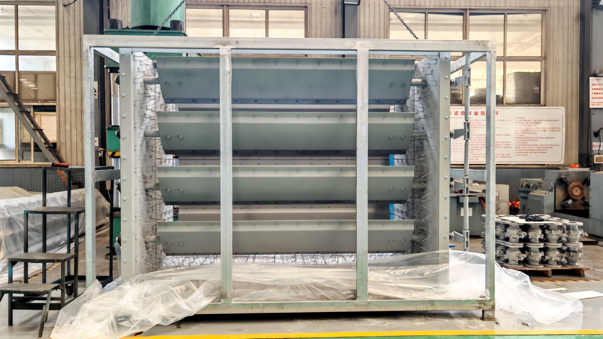
Off-the-shelf equipment rarely fits when you’re dealing with highly corrosive exhaust, extreme temperatures, or tight mechanical rooms that defy standard footprints. We develop OEM air handling configurations that start with your process parameters—not our catalog limitations—so the unit arrives ready to integrate into your existing ductwork, controls, and operational rhythm without on-site rework.
From all-welded stainless housings that handle hydrochloric acid fumes to direct-drive plenum fans tuned for a specific static pressure curve, each assembly is matched to the chemistry, altitude, and duty cycle of your application. This means no generic coatings or over-spec motors; just a system designed to your actual operating point.
What often makes the difference isn’t a single large component but the way we adapt access sections, drain placements, and lifting lugs so maintenance teams can work safely in constrained spaces. If your facility documents unusual airstream characteristics, we engineer the housing, coil layout, and fan arrangement around them rather than forcing compromises that become long-term operational headaches.
Withstanding Heat and Pressure: Material Selection Insights
Choosing materials that can reliably endure extreme heat and pressure is a quiet art, one built on understanding how substances behave when pushed to their limits. It’s not simply about picking the strongest alloy or the most heat-resistant ceramic; the real insight comes from recognizing the interplay between thermal expansion, creep resistance, and long-term stability under sustained load. Engineers often look beyond standard datasheets—watching how a material’s microstructure evolves over time, how grain boundaries might shift when temperatures climb past 1,000°C, or how hydrogen-rich environments can sneak in and degrade performance. This kind of thinking means that sometimes a nickel-based superalloy is passed over for a carefully stabilized ferritic steel, not because it’s tougher, but because it holds its shape and resists oxidation better in a specific, unforgiving set of conditions.
Practical experience also teaches that surface finishes and protective coatings can make or break performance. A turbine blade coated with a thermally grown oxide layer might survive thousands of hours longer than an uncoated counterpart, even if both share the same base composition. Meanwhile, in oil and gas applications, the choice between Inconel 718 and a high-strength martensitic stainless often hinges on threshold stress corrosion cracking data gathered not in a lab, but from field failures recorded over a decade. This hands-on knowledge—paired with rigorous testing like cyclic oxidation and pressurized creep rupture—helps teams sidestep the shiny brochure numbers and focus on the gritty realities of how joints warp, seals degrade, and mismatched thermal expansions quietly tear a system apart.
In the end, surviving high heat and pressure demands a mindset that blends skepticism with curiosity. It’s about asking what happens after the 10,000th thermal cycle, not just the first hundred. It’s recognizing that a material’s performance in a vacuum might have little to do with its behavior in a steam-laden atmosphere at 600°C. And sometimes, the most durable solution is the one that seems counterintuitive—a refractory metal that oxidizes rapidly yet forms a tenacious, self-healing scale, or a ceramic matrix composite that embraces microcracking as a way to relieve thermal shock. These insights don’t come from quick searches; they grow from iterative failure analysis, conversations across disciplines, and a willingness to look past the obvious candidates.
Positioning Dampers for Optimal System Performance
The placement of dampers within a system often dictates overall efficiency more than the dampers themselves. Even a high-quality unit can underperform if it’s tucked away in a low-flow zone or positioned where turbulence masks its readings. Recognizing this early in the design phase helps avoid costly retrofits down the line.
A common oversight is treating damper location as an afterthought—assigning them wherever there’s leftover space. Instead, mapping out pressure differentials and anticipated load shifts reveals the points where a damper can actively shape flow rather than merely react to it. In variable air volume systems, for instance, placing dampers too close to branches can starve adjacent zones during part-load conditions.
Fine-tuning involves more than just coordinates. The orientation, clearance from obstructions, and even the direction of actuator access all play into long-term reliability. Maintenance teams appreciate when dampers are reachable without dismantling duct sections, and sensors respond better when placed in laminar flow. These practical touches often separate a system that merely functions from one that stays balanced year after year.
Decoding Pressure Drop and Leakage Class Standards
Pressure drop in a valve represents the energy lost as fluid moves through the restriction, measured as the difference between inlet and outlet pressure. It’s a practical indicator of how much the valve interferes with flow—higher drops often mean more turbulence and wasted pumping power. Engineers usually express it in psi or bar and watch it closely because it affects system efficiency. What’s less talked about is how the shape of the internal passage, not just the size, can create unexpected drops, especially in partially open positions where the flow stream contracts and then expands, losing energy that a simple Cv calculation might miss.
Leakage class standards, on the other hand, define the acceptable amount of media that slips past the valve seat when it’s fully closed. These aren’t one-size-fits-all numbers—different applications tolerate different leak rates. For control valves, standards like ANSI/FCI 70-2 set specific classes based on the percentage of rated flow that leaks through. A Class IV valve might allow 0.01% of max flow, while a Class VI demands almost zero visible leakage for resilient seats. The nuance many overlook is that leakage class isn’t just about seat tightness—it also depends on the pressure differential during testing. A valve can pass at low test pressure but leak unacceptably under real operating conditions.
Bringing these two concepts together reveals a balancing act in valve selection. A low pressure drop often requires a larger valve opening, which can conflict with the need for tight shut-off at small clearances. Some engineers chase minimal leakage without realizing it forces the trim into a configuration that spikes pressure drop when throttling. The real skill lies in matching both metrics to the system’s personality—prioritizing drop across the travel range or focusing on shut-off integrity depending on whether the valve modulates or isolates. Field experience shows that noise and vibration often trace back to a mismatch between expected leakage class and the actual pressure drop envelope.
Long-Term Care for Damper Assemblies in Demanding Settings
In gritty manufacturing plants or offshore rigs where salt spray and vibration are daily realities, damper assemblies rarely fail without warning. Instead, they degrade bit by bit—blade edge erosion, slight binding in linkage pivots, or seal compression set that slowly lets conditioned air slip past. Catching these shifts early demands more than a visual glance; it calls for hands-on checks at intervals timed to the specific stresses of the environment, not a generic calendar.
Lubrication becomes a tailored craft in these settings. What works in a dry, dusty mine might gum up in a humid paper mill. Some sites thrive with thin, penetrating oils that flush grit from tight clearances, while others need heavy, tacky greases that cling under high-frequency oscillation. Picking the wrong one often accelerates wear, so it pays to lean on empirical feedback—listening for faint creaks during strokes or measuring actuator current spikes that hint at extra friction.
Over the long haul, a care program’s backbone is the logbook, whether paper or digital. Noting the date, observed condition, and any small adjustments made—like repositioning a limit switch or swapping out a deformed elastomeric seat—creates a trail that reveals patterns. One site might notice that damper A always drifts out of stroke alignment after a month of thermal cycling, triggering a proactive realignment before the drift becomes operationally noticeable. That kind of institutional memory is what keeps a critical system breathing smoothly year after year.
FAQ
Louver damper valves are mechanical devices designed to control the flow of air or gas within ductwork by adjusting a series of angled blades. In OEM contexts, these valves are custom-built to fit specific equipment, ensuring precise modulation of airflow for processes like combustion control, ventilation balancing, and dust collection.
You’ll often encounter them in power plants, chemical processing facilities, and large-scale HVAC systems. They’re essential wherever precise air regulation is needed—think boiler air intakes, flue gas pathways, or cleanroom pressurization. They also pop up in cement and steel mills where harsh, particulate-laden airstreams are common.
Customization means the valve can match exactly the duct dimensions, pressure ratings, and material requirements of your system. This eliminates retrofitting hassles and often improves seal integrity, reduces leakage, and extends service life in demanding applications. Plus, OEM designs can integrate actuators or sensors seamlessly.
Start by nailing down the operating conditions: temperature, pressure, air composition, and required leakage rate. Then consider the blade style—parallel or opposed—based on whether you need linear or quick-opening flow control. Material selection comes next, often stainless steel for corrosive environments or carbon steel for general use. Finally, factor in actuator type, installation orientation, and maintenance access.
Absolutely. By precisely modulating airflow to match real-time demand, they prevent wasteful over-ventilation or excess draft. In combustion systems, for instance, optimized air-to-fuel ratios reduce fuel consumption. Some designs also minimize pressure drop when fully open, which means fans don’t have to work as hard, directly cutting electricity usage.
Regular inspection is key—look for blade warping, bearing wear, and seal degradation. Lubricate moving parts according to manufacturer schedules, and clean any accumulated debris that could hinder blade movement. In high-temperature or dirty airstreams, more frequent checks are smart. For actuated dampers, verify linkage tightness and calibration to maintain modulation accuracy.
Conclusion
Louver damper valves play a silent but decisive role in the orchestration of industrial airflow, where even minor fluctuations can ripple into costly inefficiencies. Their ability to deliver precision airflow management hinges on blade geometry and actuator responsiveness, allowing operators to fine-tune volume and direction with remarkable accuracy. What elevates these components beyond off-the-shelf solutions is the depth of custom OEM engineering available today—manufacturers routinely adapt frame dimensions, blade profiles, and seal materials to accommodate unconventional ductwork or aggressive media. Material selection becomes equally critical when systems push into extreme temperature or pressure regimes; from stainless steel alloys that resist warping under sustained heat to specialized coatings that fend off corrosion, every choice is a calculated defense against environmental stress.
Strategic positioning of the damper within the duct network transforms it from a simple obstruction into a performance multiplier, minimizing turbulence and balancing airflow distribution across interconnected zones. Understanding the interplay between pressure drop and leakage class is essential for complying with industry standards without sacrificing energy efficiency—a well-selected damper keeps unintended air escape well within acceptable limits while maintaining manageable resistance. In demanding settings like power plants or chemical processing facilities, longevity is not a given; it demands a regimen of inspection, lubrication, and seal replacement that accounts for thermal cycling and particulate buildup. Mastery of industrial airflow regulation then, is not a single purchase or design choice, but a continuum—where material intelligence, custom fabrication, and vigilant maintenance converge to keep air moving exactly as intended, year after year.
Contact Us
Contact Person: Su Zhang
Email: [email protected]
Tel/WhatsApp: +86-25219206
Website: https://www.tht-valve.com/