

Top Robotic Bending Techniques Enhancing Precision in Metal Fabrication
2026-10-25
Precision in metal fabrication isn't just a goal—it's a necessity. Yet traditional bending methods often fall short, leaving fabricators wrestling with springback, material distortion, and inconsistent angles. Robotic bending has changed the calculus, but which techniques actually deliver measurable gains? From adaptive path correction to real-time force feedback, this post unpacks the top robotic bending methods that separate high-precision shops from the rest. Along the way, you'll see how HUNSONE integrates these very techniques into its systems, turning complex bends into repeatable, near-perfect results. If you've ever wondered what truly drives accuracy in modern metal forming, keep reading—the answers might challenge your assumptions.
Adaptive Angle Correction Responds to Material Hardness Changes
When a cutting tool meets a workpiece, the ideal contact angle isn't fixed—it shifts as the material's resistance changes under pressure. Softer alloys tend to deform and wrap around the edge, demanding a more aggressive rake to slice cleanly rather than smear. Hardened steels, on the other hand, punish any excess angle with chipping or sudden edge failure. Adaptive angle correction interprets this feedback in real time, nudging the tool's attitude just enough to keep the cut stable without overcompensating.
The mechanism relies on a continuous loop of force sensing and micro-adjustment. Imagine the tool holder measuring subtle variations in torque and vibration, then tilting the insert a fraction of a degree while the spindle is still spinning. That small shift redistributes the cutting load, reducing heat concentration and extending edge life. It's not about chasing a perfect static geometry—it's about accepting that material hardness is never uniform, and letting the tool's posture follow the reality of the cut.
For operators, this translates into fewer manual offsets and less guesswork when switching between batches. A job that starts with annealed stock and moves into case-hardened sections no longer requires a pause to reset parameters. The system adapts to each change in density, keeping chip formation consistent and surface finish predictable. It's the difference between forcing a predetermined path and listening to what the material is actually telling you.
Automated Tool Changes Eliminate Setup Bottlenecks
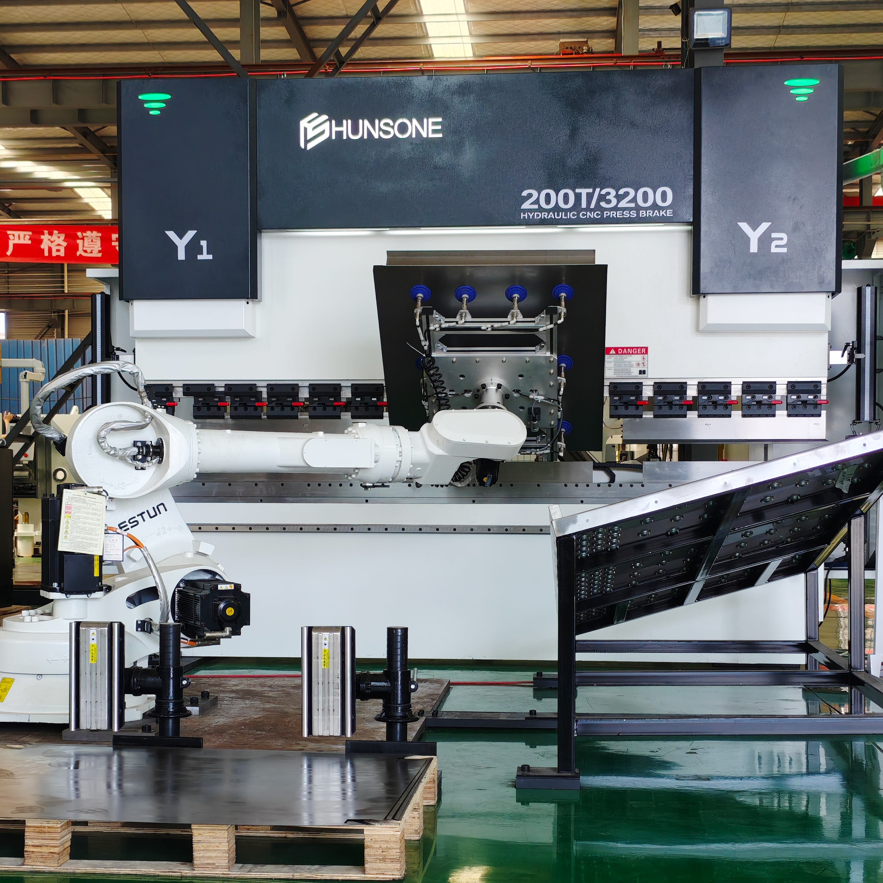
Manual tool swaps often mean shutting down the spindle, waiting for an operator to fumble with collets and wrenches, and then re-zeroing before the next cut. That downtime adds up quickly, especially in high-mix, low-volume shops where changeovers happen several times a shift. Automated tool changers sidestep this entirely by pre-staging tools in a magazine or turret and swapping them in seconds under program control. The result isn't just faster transitions—it's a continuous, predictable machining rhythm that keeps setups from becoming the bottleneck they so often are.
What tends to get overlooked is how much setup time is actually lost to non-cutting activities: clearing chips, verifying offsets, touching off tools, and walking back to the control. An automated system removes the variability that comes with operator-dependent routines. Instead of a four-minute manual change that might stretch to ten on a bad day, you get a repeatable, documented exchange that happens the same way every time. That consistency frees up the operator to run a second machine, stage the next job, or handle quality checks—turning what used to be dead time into productive parallel work.
For shops running lights-out or with a lean crew, automated tool changes are less a convenience and more a requirement. They allow unattended machining across multiple operations without an operator hovering nearby. Paired with probing and tool life management, the machine can call up a fresh tool before wear affects the part, keeping tolerances tight without interrupting the cycle. The setup bottleneck doesn't just shrink; it disappears, replaced by a workflow where the machine keeps cutting and the next job is already staged before the current one finishes.
Force-Based Bending Models Predict Springback Accurately
Traditional finite element simulations often overestimate springback because displacement-based elements impose kinematic constraints that smooth out the through-thickness stress gradients responsible for elastic recovery. Force-based bending models avoid this pitfall by interpolating internal forces rather than displacements, satisfying equilibrium pointwise along the member. This allows the model to retain sharp variations in residual stress after forming, which are the primary driver of springback.
A key advantage of force-based formulations lies in their fiber-section integration. The cross-section is subdivided into a large number of fibers, each following its own uniaxial stress-strain path under cyclic bending and unbending. This captures the progressive movement of the neutral axis and the development of a non-linear stress profile through the thickness. When coupled with advanced hardening laws such as the Yoshida-Uemori model, the force-based approach accurately reproduces the Bauschinger effect, transient softening, and work-hardening stagnation that strongly influence springback magnitude.
Experimental validation on draw-bend tests and U-channel forming shows that force-based bending models predict springback angles within a few percent of measured values, whereas conventional shell models can err by over twenty percent. The improved accuracy stems from not averaging out local stress concentrations and from enforcing equilibrium across the entire section at every load step. Consequently, tooling compensation can be determined with far fewer die tryouts, saving both material and lead time in sheet metal forming operations.
Offline Simulation Replaces Trial-and-Error First Runs
Before offline simulation became practical, engineers had no choice but to load a new program into a physical machine and watch what happened. The first run was rarely clean. Tool paths collided with fixtures, servo tuning caused violent oscillations, and cycle times missed targets by wide margins. Each failed attempt meant stopping production, adjusting parameters by feel, and starting over. On a busy factory floor, this trial-and-error approach could burn an entire shift just to get one cell running acceptably.
Offline simulation turns that process inside out. A detailed digital twin of the machine, tooling, and workpiece lets engineers run hundreds of virtual first runs before any real metal moves. Collision detection flags interference between the spindle and clamps. Kinematic models expose reach limitations and singularities that would otherwise crash the arm into a wall. Cycle time estimates reveal bottlenecks in the motion profile. Instead of guessing at feed rates or acceleration values, the team adjusts them in the simulated environment and immediately sees the result.
The payoff shows up most clearly during commissioning. Machines that once required days of on-site debugging now reach production speed in hours. Because the virtual runs already eliminated the obvious mistakes, the first physical run behaves more like a second or third iteration. Maintenance windows shrink, scrap parts from setup errors drop sharply, and operators gain confidence in programs they have already seen succeed on screen. Offline simulation does not remove all uncertainty, but it pushes the trial-and-error phase out of the real world and into a risk-free digital space.
Vision-Guided Alignment Locks Parts in Micron-Level Position
The core of this approach is a camera system that continuously compares the live position of each component against a reference image. Instead of relying on fixed mechanical stops, the controller makes tiny corrections along X, Y, and theta axes until the alignment features—such as crosshairs or edge patterns—fall within a two-micron window. This closed-loop feedback removes the stack-up errors that usually come from part tolerances, fixturing, or temperature drift.
Once the vision system confirms the target position, the locking stage engages without disturbing the placement. A low-force clamp or vacuum nest holds the part steady while the servo drives disengage, so the alignment is preserved as a physical state rather than an active correction. The lock is designed to resist vibration and thermal expansion, which are the biggest enemies of micron-level stability in a running assembly line.
In practice, this method proves most valuable in processes like optical module bonding or micro-electromechanical system (MEMS) packaging, where a few microns of shift can ruin performance. Operators no longer need to shut down the line for manual tweaks; instead, the vision-guided lock holds each part in its ideal position throughout curing, welding, or adhesive setting.
Closed-Loop Inspection Inside the Robot Cell
Inside the robot cell, closed-loop inspection turns every machined part into a source of real-time process data. Cameras or laser scanners mounted near the robot end-effector check critical dimensions while the part is still fixtured, so any drift shows up immediately instead of after a batch has left the line.
The inspection results feed directly back to the CNC or robot controller. If a bore diameter trends toward the lower tolerance limit, the system can trigger a tool offset update before the next cycle rather than waiting for a manual adjustment. This keeps variation tight without stopping production.
Because the loop runs in-cycle, scrap and rework drop noticeably. Operators see flagged deviations on a dashboard with recommended corrective actions, which helps them act on exceptions rather than inspecting every piece.
FAQ
In robotic bending, automatic angle correction relies on feedback from laser scanners or probe sensors placed right after the bend. The robot measures the actual angle, compares it with the target, and adjusts the next stroke or the robot's positioning in real time. Without this loop, springback variations in the metal would cause small but costly deviations. It matters because even half a degree of error can throw off downstream assembly or weld fit-up.
Offline programming builds the entire bending sequence in a simulated environment using the exact CAD model of the part, the tooling, and the robot kinematics. The bending path, gripper positions, and collision checks are all validated before the robot ever moves. Teach-pendant methods, by contrast, often rely on manual jogging and trial bends, which introduces human inconsistency. Offline programming reduces that variable and lets you hit tight tolerances on the first production run more often.
Laser angle measurement systems and six-axis force-torque sensors tend to deliver the most consistent results. Laser systems capture the actual bend angle within milliseconds and feed corrections back to the robot controller. Force-torque sensors detect how much pressure the robot applies when handling or repositioning the part, which helps avoid micro-slippage. Together they keep the process stable even as tooling heats up or material thickness shifts slightly.
Springback management usually combines material-specific bend algorithms with live angle feedback. The controller stores baseline springback data for different alloys and thicknesses, then adjusts the bend depth or dwell time accordingly. When the robot measures the part after forming, it can make a fine correction pass if the angle is outside tolerance. This closed-loop approach is far more reliable than relying on fixed overbend values, especially with materials that behave inconsistently between batches.
The gripper holds the part while the press brake forms it, so any unwanted movement shows up as dimensional error. Adaptive grippers with adjustable finger positions and controlled clamping force help the robot maintain a stable reference without squeezing the metal hard enough to leave marks or introduce twist. Some cells use vacuum or magnetic grippers for thin or coated sheets, which reduces the risk of surface damage and keeps the part aligned through multiple bends.
It can significantly improve high-mix, low-volume work if the cell is set up with quick-change tooling and offline programming. The robot doesn't get fatigued or lose focus between different part numbers, so repeatability stays high even when the batch size is small. The main challenge is the upfront programming and calibration time, but once a library of proven bending routines exists, switching from one part to another becomes faster and less error-prone than manual setups.
Tool center point calibration defines the exact position and orientation of the robot's end effector relative to the bending tool. If this calibration drifts by even a fraction of a millimeter, the robot will place the part slightly off the die, causing uneven flanges or inconsistent angles. It's overlooked because the error can be too small to see by eye, but it becomes obvious in the final measurements. Regular calibration after tool changes, collisions, or thermal shifts is one of the cheapest ways to protect accuracy.
Real-time monitoring tracks angle, force, and position data for every single bend. When a measurement falls outside the expected range, the system can flag the part before it moves to the next station, preventing a small deviation from turning into a full batch of rejects. It also builds a historical record that helps identify drift trends, such as tool wear or temperature effects, so maintenance can be scheduled before accuracy degrades further.
Conclusion
Sheet metal rarely behaves the way a spec sheet says it will. Hardness shifts from one coil to the next, and a bend angle that was perfect at 9 a.m. can be off by noon. Robotic bending cells handle this through adaptive angle correction that reads the force curve during the bend and adjusts the punch depth on the fly. By linking that feedback to a force-based bending model, the robot predicts springback before the final stroke, so it compensates for the material's elastic recovery instead of hoping a fixed overbend value will work. Automated tool changes have also removed a tedious bottleneck: the robot now swaps punches and dies between jobs, eliminating the setup time and alignment drift that human tool loading introduces.
Meanwhile, offline simulation means the first physical part is rarely a guess. The software runs through the entire bend sequence, checking robot reach, tool clearance, and collision risks, so programmers can fix the process without burning blanks. When the sheet lands on the table, vision-guided alignment takes over, using edge profiles or etched fiducials to nudge the part into a repeatable, micron-level position. From there, closed-loop inspection inside the cell completes the loop: a laser scanner or touch probe checks the formed angles and key dimensions right after the bend, and the controller either re-strikes the part or flags it before it leaves the station. The result is a bending process that behaves less like traditional sheet metal work and more like precision machining.
Contact Us
Contact Person: James Chen
Email: [email protected]
Tel/WhatsApp: 86 13770803946
Website: https://www.hunsone.com/