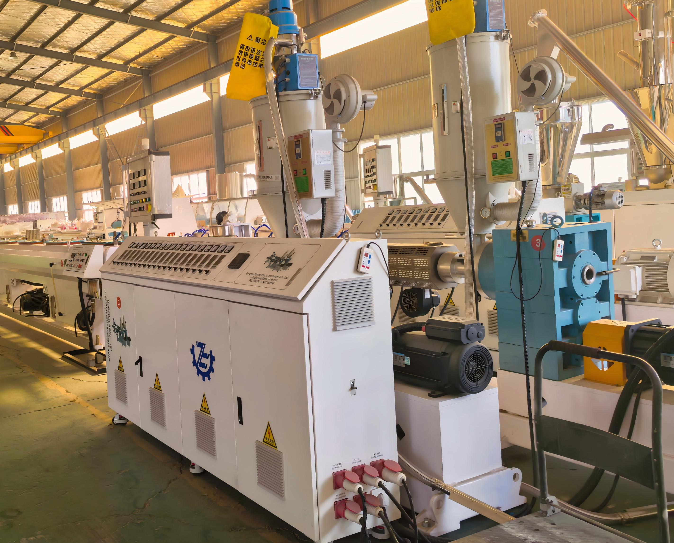

WPC Profile Machine Manufacturer Selection Factors for Consistent Production Quality
2026-11-17
Most buyers start their WPC profile machine search with output numbers and price tags. But when profiles come off the line with inconsistent density, wavy edges, or color drift, those initial specs rarely explain why. Consistent production quality depends on less obvious factors: how screw geometry handles wood-plastic compounds, how tightly barrel temperatures are held, how the calibration stack is engineered, and how quickly the manufacturer responds when a run goes wrong. That turns machine selection into a long-term bet on engineering capability rather than a simple purchase decision. In this article, we unpack the criteria that separate reliable systems from costly compromises—and why Yongte builds its lines around repeatable, shift-after-shift output.
Vent Port Efficiency When Moisture Spikes
Most vent ports are sized for steady airflow, but the behavior shifts once humidity climbs quickly. The pressure differential that drives air through the opening changes as water vapor alters air density near the membrane, and the first signs usually appear as sluggish equalization after a rapid temperature swing.
Condensation is the larger variable. When moist air reaches the port, small droplets cling to the edges and reduce the usable open area far more than a basic humidity reading would suggest. A port that breathes freely at 60% relative humidity can become noticeably restricted at 95%, especially if the surrounding housing is cooler than the incoming air.
Treating the port as a dynamic opening rather than a fixed orifice leads to better decisions. Adding a small buffer volume or using water-repellent vent media helps, but the real safeguard is checking performance at the highest expected dew point rather than at comfortable averages. That is when the differences in vent port efficiency become obvious and expensive.
Screw Geometry Matched to Your Actual Formulation
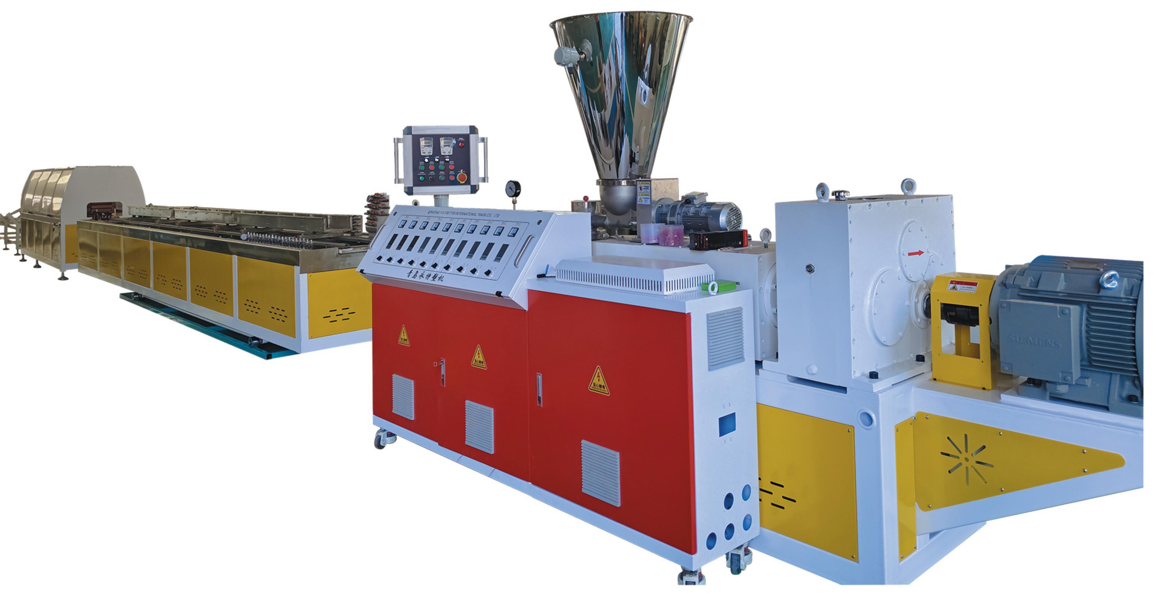
Twin-screw extrusion often fails because the screw design was borrowed from a generic playbook rather than derived from your specific material behavior. Shear sensitivity, melt viscosity under load, filler particle shape, and even the way a formulation releases moisture during plastication all change how flight depth, kneading block stagger, and pitch progression should be arranged. Matching geometry to the actual formulation means starting with rheology and thermal history, not with a catalog number.
A paste-like ceramic slurry demands a very different energy input profile than a glass-fiber-reinforced engineering resin. The former may require low-shear conveying and gentle distributive mixing to avoid binder separation, while the latter needs intensive dispersive kneading to break fiber bundles without excessive heat buildup. When the screw profile is tuned to these real behaviors, you see fewer dead zones, lower barrel temperatures at the same throughput, and far less variation in pellet quality across a shift.
The practical advantage is that adjustments become predictable. Instead of guessing whether a reverse element will overwork the melt, you can use measured pressure differentials and exit melt temperatures to shape the next profile iteration. Over time, this creates a geometry library tied to your own formulations—not an idealized demo compound—so every new product development project starts from a proven mechanical baseline rather than a trial-and-error loop.
Thermal Mapping Along Every Barrel Zone
A barrel is rarely uniform in temperature, even when it looks stable from the outside. Thermal mapping tracks heat distribution across the feed throat, compression zone, metering section, and the tip. The goal is not to chase a single ideal number but to understand how each zone drifts under load, during purges, or after screw-speed changes. Operators who rely only on the controller display miss slower drift patterns that show up clearly once you map the entire length.
Small differences between adjacent zones often matter more than a single hot spot. A cooler feed zone can force the downstream zones to work harder, raising melt temperature and degrading additives before the product ever reaches the die. By recording temperatures at regular intervals, you start to see these relationships instead of reacting to alarms. It also helps to compare readings against the setpoint while the extruder is running, not just during idle warm-up.
The most useful maps are built over time, in the same conditions you actually run. Thermal tape, contact probes, and infrared readings each tell part of the story, but none should be trusted alone. Keeping a consistent measuring pattern along the barrel lets you spot heater failures, worn screw sections, or cooling-channel blockages before they become production problems.
Tooling Tolerances That Hold Over Long Runs
Keeping a tight tolerance for a few dozen parts is one thing. Holding that same number across thousands of cycles without constant adjustment is another challenge entirely. The tools that manage this tend to share a few quiet habits: balanced cutting forces, controlled chip evacuation, and inserts that wear in a predictable direction rather than drifting unpredictably. When these details line up, the process stops fighting itself and starts repeating the same geometry almost without thinking.
Long-run consistency also depends on how heat moves through the setup. A holder that grows a few microns too early in a shift can push a bore or shoulder out of spec before anyone notices. Shops that avoid this tend to rely on thermal symmetry, coolant aimed at the same spot every cycle, and occasional in-process checks that don't interrupt the rhythm. The goal is not perfection on the first part, but a predictable envelope that stays put from morning to afternoon.
What separates a capable tool from a frustrating one is often how it handles cumulative wear. Instead of demanding constant offsets, a well-designed edge geometry lets the machine hold size until the insert is nearly spent. That buys minutes at the control panel and keeps operators from chasing numbers all day. In the end, tolerances that hold over long runs are less about heroic effort and more about removing the small variables that invite drift.
In-Line Process Data Without Operator Guesswork
Production lines still lean heavily on operator judgment, even when the process itself is far too fast to read by eye. A slight shift in clamp pressure or coating weight can go unnoticed until a downstream check fails. In-line process data removes that lag by pulling measurements straight from the line, giving the team a current picture instead of a best guess.
What makes the approach practical is that the data arrives as the work is happening, not after a batch has moved on. Operators can see a temperature or thickness trend the moment it starts to wander and make a small correction before scrap accumulates. The conversation on the floor changes from “what do you think happened” to “here is where it moved.”
That shift also reduces the burden on shift notes and memory. When every parameter is captured continuously, root cause becomes a matter of looking at the data rather than reconstructing timelines. Consistency improves because the process is visible to everyone, and the operator’s skill is spent interpreting clear signals instead of filling gaps.
Supplier Response When Output Starts to Drift
A sharp supplier usually catches output drift through its own in-process checks before the customer ever sees a bad part. The first move is to quarantine the suspect material and pull the run history for that shift, looking for anything that changed: a new operator, a rebuilt fixture, a slightly different raw material lot, or even a temperature swing on the floor. That containment happens quickly because releasing borderline product only makes the correction harder later.
From there, the supplier works backward through the process to separate a genuine shift from ordinary noise. Often the issue comes down to something unglamorous like a worn cutting edge, a clogged nozzle, or a sensor that was slowly losing calibration. Once the likely cause is identified, the supplier runs a short confirmation batch, checks the output against a known-good reference, and holds new shipments until the readings settle back into the expected band and stay there across several consecutive samples.
The response is not finished when the line starts running well again. A clear note goes to the customer explaining what drifted, what was done to correct it, and which controls were added or tightened so the same failure does not quietly return. The best suppliers treat a drift event as proof that the process was not as stable as assumed, not as an inconvenience to be papered over.
FAQ
Focus on screw geometry, barrel venting, temperature control zones, die flow balancing, calibration tooling accuracy, and puller speed regulation. A machine that holds melt temperature within a narrow band and delivers uniform melt pressure will reduce density shifts and dimensional drift far more than a long list of add-on features.
Ask for trials using your worst-case raw material, not their optimized demo blend. Look for a two-stage screw with a vent that stays clean over several hours, moderate compression, and wear-resistant barrel coating. If the supplier cannot show stable amps and melt pressure with your real material, consistency will suffer once you run production batches.
Rated output rarely reflects thermal homogeneity or pressure stability. Differences usually come from poor melt temperature control, uneven die land distribution, weak vacuum calibration, or puller slippage. Those issues cause density variation, shark skin, edge tearing, or hollow sections even when the extruder is technically producing the specified kilograms per hour.
You need rigid calibration blocks with enough vacuum slots and dedicated water circuits for each profile face, not a generic tank. The first meter after the die matters most: rapid, even skin cooling locks dimensions before sagging or shrinkage takes hold. Also confirm the calibration table can be aligned and locked quickly between runs so operators do not compensate by changing puller speed.
It is usually safer for accountability, but not mandatory if each supplier has proven interfaces. If you mix brands, define who owns the final profile tolerance and who responds when the die, calibration, and puller do not work together. A single source reduces finger-pointing, yet a specialist die maker may outperform a general line builder if the integration is properly managed.
Look for closed-loop barrel and die zone control with fast response, melt pressure and melt temperature sensors before the die, automatic line speed synchronization, and data logging. The ability to recall exact recipes prevents operator adjustments from drifting over shifts. Alarms for pressure deviation and barrel overheat are more useful than a large touchscreen with limited process visibility.
Slow spare parts delivery for wear items like screws, barrels, calibration plates, and puller pads causes rushed changes and unstable startups. Check response time for process troubleshooting, availability of remote diagnostics, and whether the supplier keeps a service history for your line. A manufacturer that treats support as a training issue, not just parts sales, will help you maintain stable settings instead of constantly chasing defects.
Conclusion
Choosing a WPC profile machine builder is less about glossy spec sheets and more about how the equipment behaves when raw material moisture swings upward. A well-designed vent port should pull volatiles out before they turn into surface defects or hidden voids, and that capability becomes obvious only when you run a batch that arrives wetter than usual. The screw geometry also needs to line up with the specific filler-to-polymer ratio in your plant, not a generic wood-plastic blend. If the compression and mixing zones were not matched to your actual formulation, you will fight either unmelted pockets or excessive shear every shift. Barrel temperature control matters just as much; thermal mapping should show stable readings across every zone, with no unexplained cold spots near the feed throat or hot bands near the adapter.
Beyond the extruder itself, tooling tolerances determine whether profiles stay within dimensional limits after thousands of meters, so look for manufacturers that can show measurable wear data rather than promising tight numbers on day one. In-line process monitoring should record melt pressure, melt temperature, and line speed continuously, reducing the temptation for operators to make seat-of-the-pants adjustments. And when output does start to drift, the supplier's response time and diagnostic approach tell you more than any initial installation support. A manufacturer that can read your trend data, identify the root cause, and recommend corrective action without blaming raw material variability is the one worth keeping.
Contact Us
Contact Person: Ms Qin
Email: [email protected]
Tel/WhatsApp: 8613583233866
Website: https://www.yongteplast.com